When demand drives innovation, the state of the art can progress quite rapidly, but if the demand is not there yet, the end result is often the proverbial “solution in search of a problem.” One of the most prominent examples of this is the lithium-ion battery, which was developed in the 1970s, but didn’t really achieve commercial success until the mid-90s, when laptop computers and mobile phones started demanding better batteries (now EVs are adding to that demand, of course). The same dynamic applies to the two most commonly used motors in EVs: the polyphase induction (ACIM) and permanent magnet synchronous (PMSM) types. Prior to the rise of the EV, pretty much every ACIM was used as a prime mover industrially (that is, running other machines), while the PMSM type was only available in relatively small power ratings for use as servomotors (that is, to precisely and repeatably position things like milling machine tables, welding robots, etc). There was some call to make the PMSM as light and compact as possible—it often had to move itself along with whatever it was driving—but no industrial customer really cared if a 7.5 kW (10 hp) ACIM had a cast-iron frame and weighed a portly 80 kg (176 lb!). In fact, massive weight was usually considered a plus. Similarly, efficiency was more of a concern for the small PMSMs, only because that allowed more power to be delivered from a given size and/or weight of motor, and it wasn’t until 1992 (the EPA act) that the first efficiency standards for motors were enacted in the US (starting at a rather dismal 74% for a 1 hp/0.75 kW 2-pole motor)!
Electrified vehicles, however, do demand motors with high efficiency in a more compact form factor and, of course, much lower weight, than almost any other application (save aviation/aerospace), and the huge number of vehicles now being sold every year—16-17 million in the US alone—provides a tremendous incentive to motor manufacturers to meet those demands. Consequently, there’s been a veritable explosion of new materials and construction techniques for motors in the last 10 years that all but dwarfs the progress made in the first 100 years of the motor’s existence. Since the state of the art is advancing so quickly, this two-part article series will concentrate on explaining why specialized materials (part 1) and different construction techniques (part 2) deliver improvements, rather than on what specific OEMs are up to.

Electrical steels
Every motor uses a time-varying magnetic field to exert rotational force (that is, torque) on a shaft, and most rely on electrical steel to direct that magnetic flux to the right place. Electrical steels are low-carbon iron and silicon alloys with a much higher bulk resistivity than pure iron (about 20 times more) to reduce eddy current losses. The price paid is an increase in brittleness and a decrease in the allowable flux density before saturating—around 1.5 T for the typical silicon steel vs ~2.2T for pure iron. Despite the high bulk resistivity of silicon steel, transformers and motors invariably require additional steps to be taken to keep core losses (that is, eddy and hysteresis) under control. Losses from eddy currents are proportional to the area of the magnetic loops, and inversely proportional to resistance (this is why a higher bulk resistivity is good), so the core of a transformer and motor armature is broken up into a stack of laminations that are insulated from each other. This minimizes the loop area (by breaking up one big loop into many smaller ones), but at the cost of losing some of the volume of active magnetic material to insulation—an issue we’ll also run into with wire shortly.
Amorphous metal
Hysteresis losses arise from a material’s resistance to a change in the orientation of its magnetic domains—sort of like magnetic friction. The only good way to minimize hysteresis losses in a given material is to reduce the size of the crystals comprising it (that is, its grain size). One processing technique that does just that is to cool the molten metal so rapidly that it doesn’t form any crystals in the first place—making it amorphous, or glass-like. These metal glasses—which go by various trade names, such as Metglas, FineMet (Hitachi), etc—have extremely low hysteresis losses, but due to the difficulty involved in making them, they only come as continuously-cast, relatively thin ribbons (50 um is typical). Turning that into a motor armature has so far proved uneconomical, but when the breakthrough occurs, the results should be impressive (keep an eye on Hitachi).
Wire and insulation
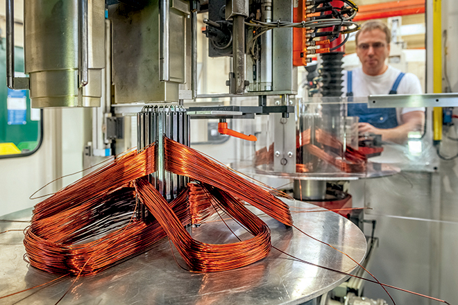
Another critical component in a motor is the wire, and the real progress being made here is not with the actual conductor material—there are really only two choices: copper, or, if you’re feeling extra spendy, silver—rather, it’s with the insulation and cabling methods. Conventional copper magnet wire is the type most commonly used in EV traction motors, and there are a whole bunch of them in parallel (aka “in hand”) to handle the high currents—as much as 1,000 A during acceleration. Despite the fact that the wires are in parallel, they are still individually insulated to reduce losses from “skin effect,” which is the tendency for alternating current to increasingly avoid the center of a conductor as frequency goes up. For example, for a motor to handle about 400 A continuous would require wire with a total cross-sectional area of around 100 square mm, which is about the same as 4/0 gauge, and a single wire of that size would start seeing increased AC resistance from skin effect at just 120 Hz. Insulation takes up valuable space in the motor, so there is considerable motivation to make it as thin as possible, but that leads to another problem (of course), which is that the fast switching of voltage by the inverter—which needs to be as fast as possible to minimize switching losses—hastens insulation breakdown and causes capacitively-coupled currents to flow across the bearings (more on that below). This has led to the development of so-called “inverter-rated” wire for motors, which was originally just a heavier application (or build) of the insulating coating. Research these days—particularly for the far more demanding EV—is focused on advanced insulating materials rather than just slapping on a thicker coat of paint, so to speak. The two key criteria for evaluating whether a new motor winding insulation is better, then, are its dielectric strength—or the voltage per unit thickness the insulation can withstand—and its dielectric loss coefficient—or how much heating is caused by the flow of AC across it. Improvements in one or both qualities must not compromise the maximum allowed operating temperature or the flexibility of the coating (its elasticity). Towards that end, fluoropolymer coatings like PVDF (polyvinylidene fluoride) and FEP (fluorinated ethylene-propylene co-polymer) will likely be increasingly adopted; in fact, these insulation materials are already being used in state-of-the-art transformer and inductor designs.
Bearings
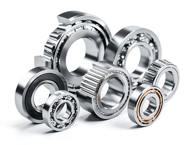
More on the mechanical end of things are advances in ball bearing technology. Much as motor manufacturers found out the hard way that conventional magnet wire insulation was failing notoriously quickly when supplied by an inverter, shaft bearings also started to see a precipitous rise in early failures, and with the same root cause (that is, the steep voltage waveforms generated by the inverter). Whenever two conductors are separated by insulation, a capacitor is formed, and the capacitor equation, I = C * (dV/dt), says that the flow of current across the insulation is proportional to the capacitance, C, and the rate of change in the voltage, dV/dt. The capacitance in a motor is between its stator windings and rotor, so capacitively-coupled currents will flow across the wire insulation—causing dielectric heating—and out through the motor bearings—causing arcing damage that leads to pitting of the bearing balls and, eventually, to total seizure. Bearing balls need to be very smooth for low friction, very tough to withstand shock and impact, and very hard to last a reasonably long time, so they are most commonly made of hardened and polished steel. If the bearing balls were in continuous contact with the races, there wouldn’t be much of a problem from capacitatively-coupled currents, but they actually ride on a thin film of lubricating oil or grease, which minimizes metal-on-metal contact and breaks the pathway between rotor and stator. This leads to charge building up on the rotor until it is sufficient to punch through the oil film (or the bearing ball suddenly makes metal-on-metal contact); in either case an arc discharge occurs, which is exactly analogous to a machining process called Electrical-Discharge Machining, hence this failure mechanism is often referred to as “EDM damage.” Making the bearing balls out of a non-conductive material and grounding the rotor through a carbon brush slip-ring are the usual solutions, but keep in mind the criteria for bearing balls outlined above: they must be smooth, tough and hard. Glass, for example, can be made both smooth and hard enough to use as bearing balls, but it isn’t remotely tough enough. Most ceramics are grainy—so they can’t be made as smooth as steel—and while exceptionally hard, also aren’t very tough. Advanced ceramic materials like silicon and aluminum nitrides, however, do appear very promising as they hit the trifecta of mechanical requirements while also being electrical insulators.
Magnets
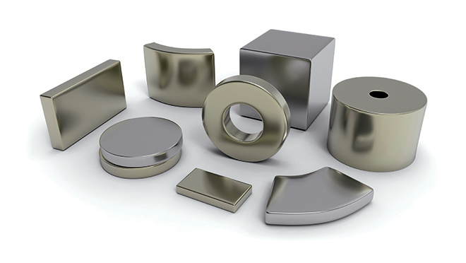
For those motors which use permanent magnets, much effort has gone into improving the maximum energy product (magnetic field strength, basically) without compromising mechanical strength, susceptibility to demagnetization and corrosion, and maximum operating temperature. As explained in a previous Charged article (“A closer look at rare earth permanent magnets”), the NdFeB (Neodymium Iron Boron) formulation is used most often in EV traction motors because it has the highest field strength (which means the most torque per amp of phase current) and is very resistant to demagnetization—as long as the temperature doesn’t get too high, that is. Just a few years ago that limit was a mere 180° C (356° F), but continuing research and development has extended it to 230° C (446° F), albeit at a steep increase in material cost and a similar decrease in maximum energy product. Since an upper limit of 180° C is just barely good enough for a typical motor (because it matches the most commonly used temperature rating of the wire insulation), further development will likely concentrate on improving the energy product and/or corrosion resistance, the latter being another real problem with the NdFeB formulation. The really interesting stuff being done with magnets has more to do with how they are squeezed into the motors beyond the basic mounting on the surface of the rotor, but that—along with other advanced construction techniques—will have to wait until part two.
This article appeared in Charged Issue 48 – March/April 2020 – Subscribe now.
source https://chargedevs.com/features/specialized-motor-materials-and-constructions-part-1/
No comments:
Post a Comment