
Avoiding motor demagnetization: John Wanjiku, Technical Specialist at Mentor Graphics, explains the goals of a detailed traction motor design analysis.
Neodymium permanent magnets are used in EV traction motors because of their powerful magnetic fields and relatively strong resistance to demagnetization, but they tend to lose their magnetism when exposed to excessive operating temperatures, opposing magnetic fields or electrical faults. This could lead to a temporary loss of torque or, in severe cases, premature motor failure.
How can engineers ensure that the motor’s magnets won’t degrade because of these factors? Charged spoke with John Wanjiku, a Technical Specialist at Mentor Graphics, a subsidiary of Siemens, and he walked us through a detailed traction motor demagnetization analysis that he recently completed.
“One of the key materials that is used in a traction motor is the permanent magnet,” Wanjiku told Charged. “But this is its Achilles heel: it degrades when operated beyond its permissible temperature. So, for high-temperature operations, if the motor is overloaded or a fault occurs, it gets demagnetized, and the capacity for that machine to generate torque dissipates. This can be instantaneous, or it can be gradual, where the motor’s capacity erodes over time.”
Defining the life, load and duty cycle of a motor
“For our analysis,” Wanjiku continued, “we use the FreedomCAR 2020 torque-speed profile (shown in Figure 1) as the benchmark for a motor’s service life. To meet the vehicle’s specifications, a traction motor must sustain 30 kW of continuous power and deliver 55 kW of peak power for at least 18 seconds. Under these conditions, the motor should last for at least 15 years or 300,000 km (about 190,000 miles) which is the vehicle’s lifetime.”
Ideally, engineers would like an EV motor that is designed to meet the peak torque demand, but doing so would require a motor that’s large, heavy, and expensive—a trifecta of undesirable qualities for an EV powertrain. Wanjiku told us that a smaller, lighter, and less costly motor—one that’s capable of delivering continuous-duty performance efficiently and can occasionally be overloaded when rapid acceleration is needed—is preferable. However, that will require active cooling to ensure that the motor doesn’t exceed its maximum operating temperature when pushed into the overload condition. As we’ll see in Wanjiku’s example, excessive temperature and overloading can permanently damage a traction motor.
Figure 2 is an example of a high-acceleration aggressive driving schedule that results in the intermittent loading of a traction motor. The load variations between 0 and 200 seconds and between 500 and 600 seconds will cause temperature cycling, which accelerates aging. So, a motor’s duty cycle is an important factor in reliability analysis.
Insulation and temperature limits
“At constant speed, the motor will settle at a steady-state temperature because there are no inertial loads,” explained Wanjiku. “In cruise control mode, you mainly have to overcome the drag force to maintain the speed. But when you accelerate or decelerate, inertia comes into play. Hence, the motor’s insulation class and thermal design are critical for intermittently loaded motors, such as traction motors.”
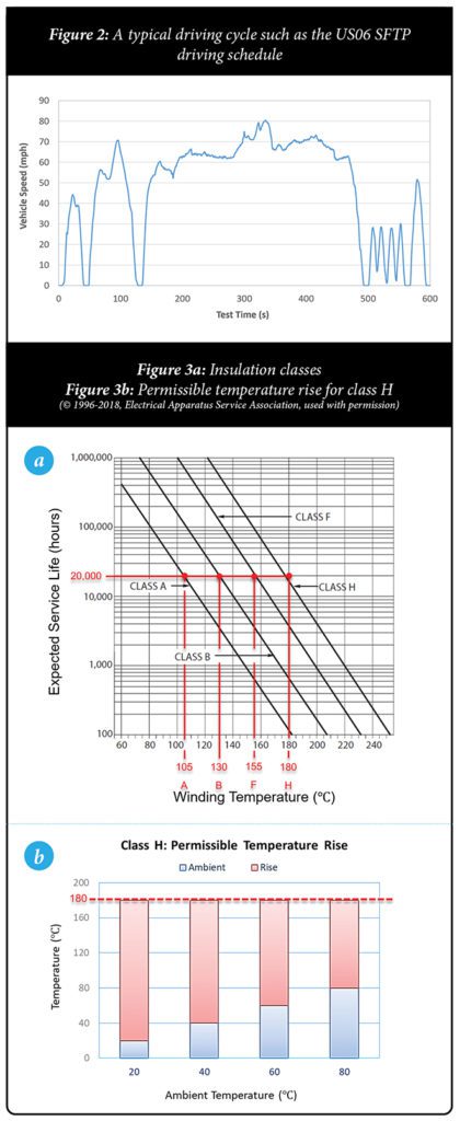
“This is because a motor’s temperature limit determines its peak torque capability and service life,” he continued. “So, the designer selects the insulation class according to the budget and expected motor life, and that, in turn, determines the highest operating temperature, as shown in Figure 3a. For our discussion, we’ll choose a class H insulator, which has a 20,000-hour lifespan as long as its temperature doesn’t exceed 180° C.” (Note: 20,000 hours is equivalent to driving an average of 3.5 hours a day for about fifteen years.)
Conventionally, the motor service life is based primarily on the class of the insulators that are used to build it. Figure 3a tells us:
- For a given winding temperature limit, the higher the class, the longer the service life.
- As the winding temperature in a given class increases, the service life decreases exponentially. (Note that the Y-axis is on a logarithmic scale.) In this case, for every 10° C increase in temperature, the insulator’s life is cut in half.
“The insulation class is based on the lowest class of the insulators used to build the motor, such as the wire enamel coating, slot-liners, impregnating varnish, etc,” explained Wanjiku. “In addition to this, permanent magnet grades have their own operating temperature limits. Since most EV traction motors are permanent magnet motors because of their higher power density, efficiency and power factor, the temperature limit must consider both the insulation class and the permanent magnet material.”
“EV traction motors are expected to operate in ambient temperatures between -40 and 105° C,” he added. That is, the ride experience should be independent of the location. “Figure 3b shows that as ambient temperature increases, the permissible temperature rise (due to loading) decreases. So, to meet the same load torques at higher ambient temperatures, the motor must be adequately cooled to keep its winding temperature below 180° C.”
Demagnetization
To minimize weight, most EVs employ permanent magnet motors rather than induction motors. However, magnet materials not only degrade with an increase in temperature but also in strong opposing fields, such as the magnetic field induced by the stator’s coils, which is increased during higher speeds (field weakening), overload and fault conditions.
Wanjiku described Figure 4a, which shows flux density (B) vs coercive force (H) at different temperatures. “We can see the demagnetization characteristic of this particular material. The dashed lines represent a linear model, which assumes that the magnetic field will recover once the coercive force is removed. The solid lines, however, acknowledge that there’s a point of no return—the ‘knee’ of the curve—at which the magnet will be permanently damaged. At higher temperatures, the knee is reached with less coercive force.”
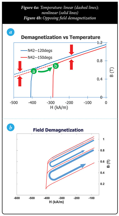
In other words, the higher the temperature, the easier it is to permanently damage the magnet through coercive forces caused by opposing magnetic fields.
“Figure 4b,” he continued, “shows the progression of a magnet’s characteristic when an opposing sinusoidal field is applied to it. In every half cycle, the external field pushes the magnet beyond the knee, making it recoil in a new, but lower, characteristic, indicating a loss of magnetization.”
We can see that the magnet’s material affects a motor’s maximum operating temperature, which, in turn, limits its peak torque capability. Since magnetization loss is permanent for high-energy traction motors, engineers must verify that their motors can withstand increases in peak demand as well as temperature in order to prevent demagnetization.
Demagnetization analysis
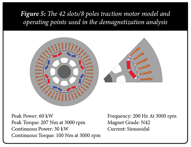
“An electromagnetic reliability assessment should include a realistic demagnetization analysis that considers both current and temperature effects under normal loads, brief overloads (e.g. up to 18 seconds), and extended-speed operations,” explained Wanjiku. “In the following analysis, we used Siemens’ Simcenter MAGNET software to model the various scenarios for a motor similar to that of a 2010 Toyota Prius. The model was reduced to a 2D pole section shown in Figure 5 and analyzed at the operating points specified in the table.”
Scenario 1: Peak demand
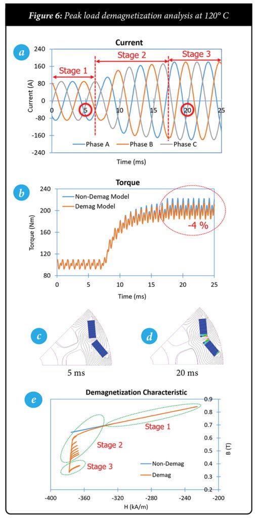
The purpose of this analysis is to ensure that the magnets are not degraded because of peak torque demand. In this case, the continuous torque of 100 Nm (with the motor delivering 30 kW) was ramped up to a peak of 200 Nm (pushing the motor to 60 kW), by increasing the current as shown in Figure 6a, with a corresponding increase in torque. Two magnet models are used: the non-demag linear and the demag irreversible models. In this scenario, winding temperature is held constant at 120° C.
Wanjiku interpreted Figure 6c: “We can see the state of the magnet before and after increasing the current. At 5 ms, the motor is operating in continuous mode, and the magnets are not demagnetized. But at 20 ms, which occurs after the current reaches its peak, the motor experiences partial demagnetization, which lowers the torque by 4%.”
So, what happened to the magnets in the partially demagnetized regions? Wanjiku told us that to analyze this, the B and H fields were sampled at a selected point in the partially demagnetized region. Samples were taken at all three stages of acceleration:
- Stage one is the continuous operating mode, in which the magnet recoils on the same characteristic for both the non-demag linear and the demag irreversible models, as seen in Figure 6e.
- During stage two, in which the current is ramping up, the demag irreversible model reveals that progressive demagnetization occurs as the material is pushed below the knee and recoils in a newer, but lower, characteristic.
- Finally, in stage three, we can see that the current settles at a higher value, and the magnet recoils in an even lower characteristic.
Under all field conditions at a constant temperature, the non-demag linear model that only accounts for temperature will recoil on the same characteristic, which overestimates the motor performance under peak and fault conditions. Clearly, the demag irreversible model is more accurate, as it accounts for both field and temperature demagnetization, as well as the magnetization history shown in Figure 6e. This is the reason that traction motors should be analyzed under all conditions, particularly under acceleration, which requires the motor to be briefly overloaded.
Scenario 2: Thermal and peak demand
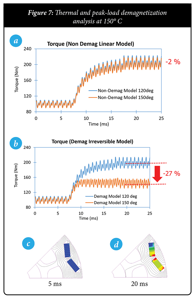
This condition is similar to Scenario 1 in terms of the current profile associated with a higher torque demand, but it also takes thermal effects into account. In this case, a higher temperature (150° C) lowers the magnet’s knee, as seen in the nonlinear curves of Figure 4a, which causes irreparable damage to occur even sooner than in the previous scenario.
“For the non-demag linear model, the effect of temperature is minimal: about a 2% overall reduction in torque (Figure 7a),” noted Wanjiku. “This is because of the slight difference in the magnet characteristic at the two temperatures, as highlighted by the arrows in Figure 4a. Remember that this model does not account for field demagnetization, so it always recoils on the same characteristic for a given temperature.”
However, Wanjiku said that under the demag irreversible model, the effect of both the higher temperature and higher current is significant: a 27% reduction in torque, as indicated in Figure 7b. This is because a combination of higher temperatures and demagnetizing currents lowers the field needed to demagnetize the magnets significantly, and it was exacerbated by the choice of the low-temperature-tolerance magnets.
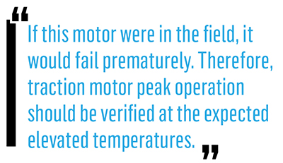
Wanjiku elaborated: “In Figures 7c and 7d, we see that at 5 ms the magnets are not significantly demagnetized, but at 20 ms, severe demagnetization results in a 27% loss of torque. If this motor were in the field, it would fail prematurely. Therefore, traction motor peak operation should be verified at the expected elevated temperatures.”
Scenario 3: Short-circuit fault
Wanjiku illustrated a situation in which a short circuit can result in demagnetization. “In Figure 8a, we see that a 5 ms short-circuit occurred at 10 ms. Figures 8a and 8b show the phase A back EMF and three-phase short-circuit fault currents, respectively.”
“Similar to the higher current demagnetization that we saw in scenario one,” he observed, “at 5 ms, no demagnetization occurs; but at 20 ms, some partial demagnetization happens after the short-circuit fault (Figures 8c and 8d). This effectively lowers the peak back EMF by about 8% (Figure 8a).”
In stage one, the demag irreversible and non-demag linear models recoil on the same characteristic. However, in stage two, with the rapid increase of the short-circuit currents, immediate demagnetization occurs at the sample point. The material is forced to recoil at a lower characteristic in stage three.
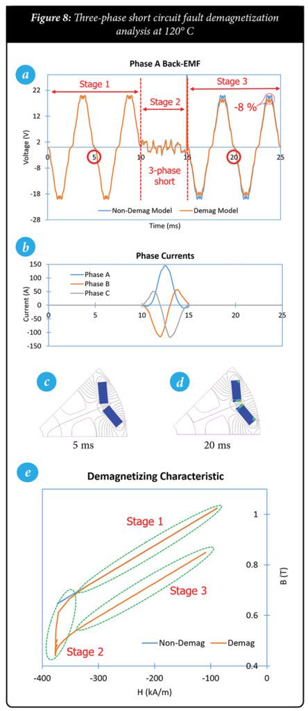
“In this scenario,” Wanjiku explained, “there is no progressive demagnetization in stage two, but a ‘jump’ to a lower magnetization state. Why is this important in fault analysis? It means that both the magnitude and the rise time of the fault currents determine the final magnetization state, and this should be factored into short-circuit fault mitigation.”
The purpose of this work is to highlight the importance of a rigorous demagnetization analysis that accurately reproduces the operating and fault conditions, allowing engineers to determine the traction motor’s operating envelope for effective monitoring, control, and fault mitigation.
By examining the demagnetization characteristics of neodymium magnets and the factors that can erode their magnetic fields, EV traction motors designers can better understand the short-term and long-term effects of excessive heat, repeated overloads, and internal short-circuits on a motor’s torque, efficiency, and motor life.
For more details about Wanjiku’s work, read the full white paper (Effects of incorporating permanent magnet demagnetization in the simulations of modern electric machines for electric vehicles), available here.
This article appeared in Charged Issue 49 – May/June 2020 – Subscribe now.
source https://chargedevs.com/features/how-to-ensure-ev-traction-motor-magnets-arent-pushed-beyond-their-operating-limits/

No comments:
Post a Comment