Tuesday, 3 March 2020

Here’s why Tesla transitioned to a semi-custom power module design in Model 3 inverter


A closer look at semiconductor packaging considerations in EVs

One of the most critical decisions to be made at the earliest stage of designing a new power converter concerns the packages used for the semiconductors, as pretty much every other aspect of the design hinges on their physical form. This is especially true for the main power converters used in EVs—on-board chargers, DC/DC converters and inverters—as there are tight constraints on the size (and cost, of course) allotted to each. Furthermore, any device that has direct or incidental contact with the AC mains will also need to meet some rather onerous electrical safety requirements which—as a case study below will show—can critically depend on the package used for the semiconductor switches.

The power semiconductor components most likely to be used in EVs come in two different form factors: (1) plastic types such as the TO-220 and TO-247 packages, which feature wire leads and a (usually non-isolated) heatsink tab, and which typically contain a single diode or switch (with or without anti-parallel diode); (2) modules, which typically contain several components pre-wired in commonly used configurations (e.g. a half-bridge plus a temperature sensor), all mounted on an electrically-isolated heat spreader. Modules also tend to have screw terminals for the high-power connections and pin or spring terminals for the low-power connections, making integration into a bused structure (and replacement of a damaged module) much easier. Despite the radical differences in their physical (and, often, electrical) aspects, there’s no clear distinction for when to choose a plastic package component or a module; using a rather broad brush to delineate between the two, modules are preferred if more than 50-100 A RMS must be handled, whereas plastic packages are preferred if switching frequency must be considerably above the ultrasonic range (e.g. >40 kHz). These are obviously very different criteria, nor are they mutually exclusive, but suffice it to say that if you need to switch >100 A RMS at >100 kHz, then you’re looking at a design challenge worthy of a PhD dissertation.

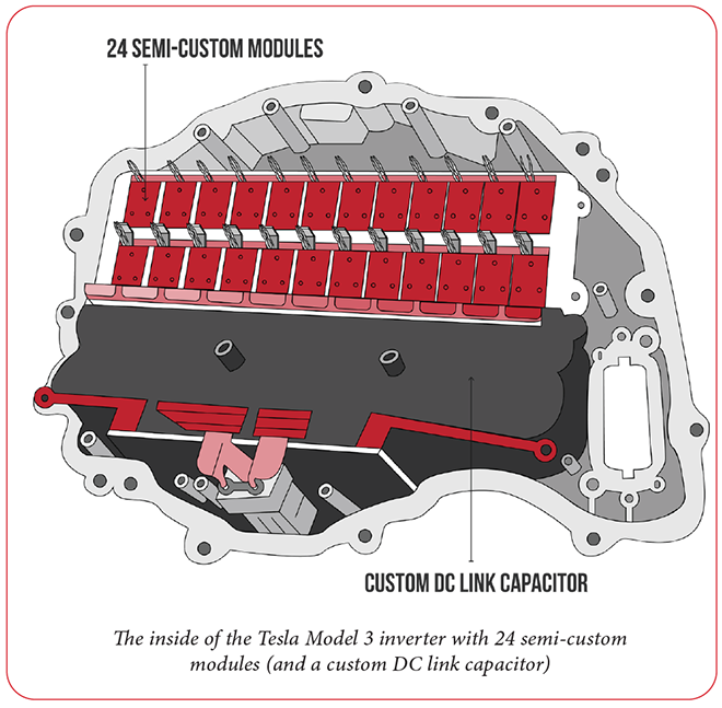
There are numerous other criteria as well as exceptions to the above rules of thumb—for a notable example, Tesla was quite fond of using dozens (84!) of TO-247 switches in its earlier inverters—but it is telling that the Model 3 inverter uses what might be called a quasi-modular approach, with far fewer devices (24) of much higher individual power rating, but still in a plastic package-like form. In fact, why Tesla might have chosen a TO-247 package device at first, only to transition to a semi-custom module later on, is precisely the subject of this article.

Prior to the emergence of OEM EVs, power semiconductor modules were designed specifically for industrial applications, with the vast majority being used in 3-phase motor drives supplied by the AC mains. Consequently, the available voltage ratings were in rather coarse steps of 600 V for 208-240 VAC mains applications, 1,200 V for 440-480 VAC, 1,700 V for 575-600 VAC, and so on. Furthermore, 3-phase motors also come in rather coarse power rating steps, so the current ratings for modules were equally coarse as well. Also, industrial applications tend to be more concerned with reliability and efficiency than with minimizing size (and the noise from “singing” motors and transformers), so the diodes and switches inside the modules weren’t particularly fast (i.e. PWM frequency rarely exceeded 10 kHz, and was usually closer to 1 kHz, especially at 1,200 V and above). Finally, while the market for all industrial motor drives is quite large, the market for any one particular voltage/current combination is relatively small, and some combinations of voltage/current just don’t make sense industrially. For example, it is possible to get 1,700 V modules rated for 3,500 A or higher, but for 600 V modules the highest current rating commonly available is 600 A. This is because no (sane) industrial customer is going to try running a >200 hp motor from 240 V mains!

Conversely, there is a veritable smorgasbord of devices and ratings in the plastic TO-247 (and smaller TO-220) packages, such that any practical combination of voltage, current and switching frequency can be had with judicious circuit design and layout (and a PCB capable of handling the current). More specifically, almost any current rating can be obtained by paralleling as many TO-247 devices as necessary…at the rate of about 20 A to 50 A per device, depending on the device technology, total losses, and how heat from said losses is removed from the junction (but note that it takes increasingly heroic measures to keep the junction temperature of a TO-247 device below 100-125° C once dissipation exceeds 50 W). For example, SiC MOSFETs have extremely low switching and conduction losses, and can tolerate operation at much higher temperatures than conventional Si MOSFETs or IGBTs, so the limiting factor on how much current can be crammed through one in a TO-247 package might very well be the ampacity of the bond-wires and/or leads. In contrast, a TO-247 IGBT with a fairly constant voltage drop of 2.2 V and comparatively high switching losses might struggle to handle 25 A, even with liquid cooling. Another factor that greatly affects the ampacity per device is that the heatsink tab on the conventional TO-247 and TO-220 packages is directly connected to the collector or drain, for IGBTs and MOSFETs, respectively, so some form of insulator will be needed between the tab and the heatsink. Unfortunately, most materials which are good electrical insulators are also good thermal insulators, such that even extremely thin sheets of mica, silicone rubber or Kapton (aka polyimide) will add around 1° C/W of thermal resistance to a TO-247 package (and up to 3° C/W for the smaller TO-220). This resistance adds to that of the junction to case and the heatsink to ambient pathways, hence the practical upper limit of 50 W dissipation per TO-247.

There are a couple of exceptions to the “good electrical insulator = poor thermal conductor” rule: aluminum oxide and nitride. The former has a bulk thermal conductivity of 30 W/m-K, while the latter clocks in at 285 W/m-K [see sidebar: Thermal conductivity vs resistance].  Both compare rather favorably to the thermal conductivity of mica at 0.3 W/m-K (or 100x to almost 1,000x worse), but aluminum nitride is an even better conductor of heat than pure aluminum (235 W/m-K), though still not as good as pure copper (400 W/m-K). Both aluminum oxide and nitride are ceramic-like materials that are hard and brittle, and also like ceramics, they are refractory (i.e. they have a very high melting point), so insulators made from them have to be relatively thick (1 mm seems to be a practical limit) compared to mica (~0.1 to 0.3 mm) or silicone rubber (<0.5 mm). Even so, aluminum oxide and nitride insulators are quite fragile. For example, a product I have helped to redesign utilizes SiC MOSFETs in a TO-247 package with 1 mm-thick aluminum nitride insulators between them and the extruded aluminum heatsink. During UL “open/short” testing (in which the UL inspector randomly opens or shorts various components, looking for potential safety issues), one of the switches exploded and shattered the aluminum nitride insulator. This allowed excessive fault current into earth ground, which is a definite fail of the test (it is perfectly acceptable for your product to quit working during this particular test, it just can’t catch fire or create a shock hazard). Changing the fuse to a faster-acting type (read: more expensive, and more prone to “nuisance trip”) sufficiently limited fault energy to less than what is needed to rupture a TO-247 package, but this is not the sort of thing you want to deal with at the proverbial eleventh hour.

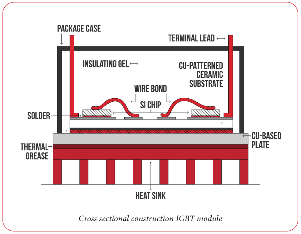
This discussion circuitously segues back to a considerable advantage of modules: the heatsink “tab” is already electrically insulated from the semiconductor dice, and the dice themselves are typically encapsulated in a special silicone gel, which both improves heat removal from the bondwires and does a decent job of containing shrapnel and metal vapor should things go pear-shaped. More specifically, the usual construction of a module is a sandwich consisting of dice soldered to intermediate heat spreaders (usually of copper) to increase the area available for transferring heat (and provide a common electrical connection between dice), followed by an aluminum oxide or nitride sheet which provides electrical isolation and, finally, a single heat spreader which also serves as the mounting baseplate. Basically, the intermediate heat spreaders lower the total thermal resistance from junction to heatsink compared to a solution using multiple TO-247 components, while the silicone gel and aluminum nitride insulators provide considerable voltage withstand rating. In fact, most (if not all) modules for industrial applications have been “recognized” by the major safety agencies (UL, TUV, Intertek, etc) for a given voltage withstand (or “hi-pot”) rating, which makes passing their tests a lot easier (by taking less time and costing less money).

As is usually the case, there are advantages and disadvantages to both types of packaging technology for semiconductors—there’s no such thing as a “one size fits all solution”—and so, unsurprisingly, none of the existing offerings are ideally suited to EV (or hybrid) applications. This is where the advanced packaging solutions conjured up for the Model 3 by Tesla and STMicroelectronics come in: a new approach to module design that combines the low-cost and reduced stray inductance of a plastic package with the electrical isolation, improved thermal performance and greater current rating per device of a classic industrial module, all with a form factor tailored for EV applications, rather than the “one size sort of fits most” of yesterday’s technology.  

SEE ALSO: A closer look at the losses in power semiconductors

This article appeared in Charged Issue 47 – January/February 2020 – Subscribe now.


source https://chargedevs.com/features/heres-why-tesla-transitioned-to-a-semi-custom-power-module-design-in-model-3-inverter/

Enevate says its silicon-dominant anode technology is ready for EV production


Q&A with Enevate’s Founder and CTO Dr. Benjamin Park

Introducing silicon into automotive-grade lithium-ion cells has been a major topic in the EV industry in the past decade. Silicon is widely considered to be the next big thing in anode technology, because it has a theoretical charge capacity ten times higher than that of typical graphite anodes. Many experts see a race among battery makers to get more and more silicon into their anodes.  

Replacing the graphite in a cell with silicon means that you can use less anode material, and fill up the extra space with more cathode material—effectively increasing the overall energy that can be stored within the same volume. This is due to a fundamental difference in the way that silicon “stores” lithium. A layered graphite structure absorbs lithium ions through a process called intercalation—it essentially consists of sheets of graphene that allow lithium ions to be stored between the layers. Silicon, on the other hand, can absorb more lithium ions, because the two elements form an alloy with a theoretical specific capacity much higher than that of graphite.

Unfortunately, practical advances in silicon anode technology have not come easily, because silicon has challenges that arise from the same attributes that make it attractive. Unlike porous graphite material, which has specific sites open and waiting for ions, when the lithium-silicon alloy forms, the structure of the anode changes, resulting in large volumetric fluctuations. For example, if a particle of silicon absorbs as much lithium as thermodynamically possible, its volume increases by about 300%. That compares to about 7% expansion observed in the intercalation of lithium into graphite.

The problem with many experimental silicon anodes is that the repeated expansion and contraction during charging and discharging leads to drastically reduced cycle life. So, to use the technology in production batteries, companies have been adding only small amounts of silicon, adding incremental benefits. Basically, they’re still primarily using synthetic graphite, while attempting to increase the amount of silicon in the anode in baby steps over time.

California startup Enevate decided to leapfrog that approach. The company set out to find a way to forego graphite altogether, and build a silicon-dominant anode. Considering that industry heavyweights including LG Chem, Samsung and Renault-Nissan-Mitsubishi have invested $111 million in Enevate to date, the company appears to be onto something. 

Enevate recently unveiled its fourth-generation XFC-Energy battery technology (that’s eXtreme Fast Charging), and says it is currently working with multiple automotive OEMs and battery manufacturers to commercialize its technology for 2024-2025 model year EVs.

Charged chatted with Enevate’s Ben Park, founder and CTO, and Jarvis Tou, Executive VP of Marketing and Products, to learn how eliminating graphite from the equation might be the key to unlocking silicon’s potential. 

Charged: Could you describe how Enevate’s approach to silicon anode technology is fundamentally different from that of other leaders in the space?

Ben Park: The first thing that’s very important to understand is that others are using evolutionary approaches, and we’re squarely in the non-evolutionary silicon box. For example, the Teslas and the Samsungs of the world are using silicon as an additive to the anode. So, even though they state that they have a silicon anode, it’s basically a graphite anode with a little bit of silicon added to it. There was a huge effort going on for many, many years that increased that percentage level of silicon. And the most common silicon that’s added to these graphite systems is in the form of SiO or SiOx as they call it, basically a silicon oxide.

There are a lot of challenges with this approach. First of all, it’s very expensive. Many of the SiO products are over $100 per kilogram. It’s basically an order of magnitude higher than graphite. That’s a problem. Second, it turns out these silicon-based materials have a problem with initial chromic efficiency. So, when you first build a battery, you’ll use up some of the lithium, and you don’t get all of that lithium back. The lithium basically leaks from the cathode, and if you add more, you’ll actually decrease the energy density of the cell. And, of course, the expansion and contraction of silicon is well known, and it causes damage to the electrode, which causes performance issues in cycle life. 

Companies are adding the silicon in terms of active material in roughly the 3-8% range, most recently, and struggling to get to 10%. 

Our approach is fundamentally different. Instead of using a graphite anode and adding silicon, we’re saying, “Let’s not use the graphite as an active material, and only use the silicon.” As far as we know, we’re the first commercial effort to do this. I think there are now other companies mimicking our approach, but we believe we’re the first.

Charged: Could you explain the technical challenges you overcame to make a functional silicon anode work without graphite?

Ben Park: Within silicon, there are multiple modes damaging the electrode. All of them are tied to expansion and contraction. So, when the silicon absorbs all of the lithium, it expands to roughly 3-4 times its original size. Obviously, that’s an issue. As you charge and discharge the battery, this causes continuous damage to the electrode and the cell. Think of it like blowing up then deflating a balloon. That’s exactly what the silicon is doing. 

Now imagine that you’re trying to hold these balloons together. You can try gluing them together with a hard glue, but if you use rubber or plastic to hold them together, it won’t hold very well, because the balloons are continuously expanding and contracting. That’s what people are attempting to do with binders. Originally, people tried to use an extremely flexible binder. If we stick with the balloon analogy, it’s like trying to use a very, very flexible rubber to hold the balloons together. When you expand the balloons, the material between the balloons will expand and contract with the balloons. So far that has not been a success, because unlike a balloon, which will always expand and contract similarly, silicon will expand and contract a little bit differently each time. It’s more like plating and de-plating, like what you see in a lead-acid cell, for example. 

We solved this problem by, first, eliminating the binder. We don’t use a polymer binder, because they’re too weak. We basically just have a film of material. Our approach has been to create an active material piece. It’s basically one piece of powder instead of a billion powder particles held together with a polymer. That way the silicon can expand and contract within an entire rigid structure, and everything is conductive. Even if there is some cracking, it won’t lose its electrical connection to the rest of the material. We went away from polymers because, no matter how rigid or flexible you make a polymer, it doesn’t seem to work. 

Our second unique solution has to do with the electrochemistry. If you combine silicon with graphite at all, you’re basically forced to use the silicon “all the way,” so to speak, and that contributes to the cycling problem. Because we don’t use any graphite, we have more options. 

Let’s say we have a graphite anode, for example, with lithiation that occurs at around 0.1 volts and lower. What that means is that, as you charge the battery, the anode voltage will be reduced, and then you have to get the voltage to 0.1 volts and lower to have the lithium go into the anode. When you charge the battery, the voltage of the battery increases, but the voltage of the battery is basically the cathode voltage minus the anode voltage. So, as the battery voltage increases, the cathode voltage is increasing and the anode voltage is decreasing. To get the graphite to actually absorb the lithium, you have to get the graphite voltage very low—let’s say below 0.1 V to simplify. Silicon will actually absorb lithium at higher than 0.1 volt—almost all of the lithium will react with silicon at a voltage higher than 0.1 volt.

That means that, if you’re creating a system where you have both graphite and silicon, pretty much all of the silicon reacts first as you’re charging the battery, and then the graphite will react later. So, in a system where you’re trying to get both graphite and silicon to work, you have to utilize the silicon fully. That means that the silicon will expand to 3-4 times its size. It will be very reactive, and will cause problems. In our case, we don’t use that graphite, so we don’t have to bring the silicon to that unstable a level. We don’t have to expand it that much, so we’re able to use silicon in a more reasonable way. We use less of it, and that’s okay because our silicon is less expensive. 

By using those two mechanisms [eliminating binders and using less of the available silicon], we were able to solve the major issues with silicon. We also have to make sure our source is readily available and inexpensive, otherwise it would have zero future in the automotive industry. We’re able to use silicon sources that are much cheaper, and much more eco-friendly, meaning a lower CO2 footprint than other companies. And that is key for the automotive industry. We were very happy that our technical approach, which enabled better electrochemical performance, also enabled better price performance and more sustainability. 

Charged: How do you control how much of the silicon in a cell is utilized during cycling? 

Ben Park: This is just something tied to the design of the battery. All of the lithium in commercial cells today comes in the cathode. Take a high-nickel material like NCA, for example—nickel, cobalt and aluminum. It’s a lithium metal oxide, and all of the lithium comes out of that cathode and goes into the anode, then back and forth. So, what we do, is we design the battery so that the lithium is limited by the cathodes in the battery. So, no matter how much you want to try to charge the battery, you can’t damage the anode.

Charged: If using it fully will expand it 300 to 400%, what would you say the expansion of the silicon in your anodes would be?

Ben Park: On a cell level, we will typically only see maybe 3-8%, which is within the realm of other graphite cells. The silicon itself will still expand 50-100%, depending on cell design. However, it’s actually absorbed within the electrode and the battery design, so you will never see that expansion from the outside. 

We don’t have a single cell design, so it’s difficult to say exactly. We choose the cathode depending on the customer. As you know, we’re involved with quite a few automotive efforts now. Each auto company and each battery company have their own preference in terms of cathodes. The good news is, our technology seems compatible with most of the cathodes out there. We have our own reference design, but so far it’s been working well with our partners’ materials and cell designs, along with our help and expertise. Those include the high-nickel cathodes that you may have heard about like nickel-rich NCA, NCM811, NCMA, low-cobalt, or other advanced cathodes.

Charged: You’ve said that your new 4th-generation XFC-Energy technology achieves 5-minute charging to 75% capacity with 800 Wh/L cell energy density. What enables such fast charging? 

Ben Park: There are multiple factors that contribute to fast charging capabilities. First of all, silicon can react faster, just as a chemical property. Think of a movie theater: if you’re trying to find a seat, it’s going to take a lot longer in a movie theater that’s almost full than in one that’s half-empty. Since we are using silicon without graphite, and we can keep a lot of the silicon empty, it’s a lot easier for the lithium to find a seat. 

The second reason is that, because we can keep the voltage higher, it’s much harder to cause lithium plating, which is a huge issue for graphite cells when you’re trying to fast charge. There are other issues as well, but those are the two main reasons.

Charged: You’re on your fourth generation of this technology. Have your previous generations been commercialized?

Jarvis Tou: Our first, second, and even third generations were originally designed for consumer electronics. We almost went to market with a cell phone manufacturer to be distributed in the US. It was fully commercialized for volume production, but we had to make a choice as a startup at that point, whether or not to launch into a production model that we would have to sustain for quite some time.

We saw this impending wave coming at us, this massive ramp of EV batteries, just dwarfing consumer electronics and everything else, so we had to ask ourselves: “Do we pivot toward EVs?” That’s ultimately what we did. We ended up not going to market in the consumer electronics space, even though it was fully commercialized. We transitioned to nickel-rich cathodes 3-4 years ago to pursue EV batteries.  Our investors directed us to focus on the EV market for the same reasons that you and I are so interested in it today—because there is this massive wave that’s just inevitable, and coming at us and dwarfing everything else.

Ben Park: With a focus on EVs, cycle life was the main thing that we’ve been improving with our technology. Now that we’ve shown a cycle life that’s acceptable to the automakers for the current stage we’re in, we’re focusing on a scale-up. Most of our efforts today are pushing towards scale-up and commercialization.

Our business model is to be a licensing company. We call ourselves a technology provider, because we often work together with the customer to implement the technologies, and we also have a significant manufacturing line where we test and collect information. Most licensing companies just have a patent, but we actually have an operational line. However, we don’t anticipate selling from the line, at least not today. Our main focus is to collect a lot of data so that we can help ramp up the larger-scale production lines, whether it’s battery manufacturers or automotive companies.

Jarvis Tou: We spend a lot of our time and effort on core R&D. Originally we were targeting to license to battery makers, but we found a shift in the EV industry, as carmakers are realizing the battery is not just a gas tank. It’s actually the powertrain or power plant for the entire EV. As Tesla has demonstrated, it dictates almost everything in an electric car. Weight, performance, handling, price, interior and cargo space—just about everything. And at the powertrain level, many automakers want control. They’re almost taking a page out of Apple’s playbook, which is to own the design of the battery and its supply chain, and license and build the core cell-level and material-level battery technology themselves, and use that as a differentiator. Then they can always contract different cell-makers to make the cells. Or have joint ventures, or even make the cells themselves. That’s what we see going on, and it could be a major shift in the industry.  

Charged: What were the main attributes that you were focusing on improving while going from third- to fourth-generation XFC-Energy battery technology?

Ben Park: We’ve made some modifications to the cathodes, but most of our improvements have been working on the process engineering to make sure everything can handle a very, very fast rate of manufacturing. For example, everybody we’re working with demands a rate of 80 meters per minute or higher, so we had to work on all the processes to make sure we could handle that.

The fifth generation will be mainly driven by further cost and safety improvements. That’s where solid-state technology may play a role. We don’t know if we actually need solid-state to meet our internal milestones. We’ve set very challenging goals—it’s kind of like the Holy Grail of battery safety that we’re working on for the fifth generation.

Charged: You’ve said that you’re working with OEMs and battery manufacturers to commercialize your technology for 2024-2025 model year EVs. Can you tell me more about the details of that timeline?

Jarvis Tou: New car platforms take 4-6 years to get to production, especially from the traditional automakers. So, we’re on that timeline now—we’re currently designing for the 2024 and 2025 model years.

Ben Park: We are also looking to release the technology in other non-automotive markets earlier. We call them gateway markets. It’s very critical to get the technology out there quickly, and to learn from the technology before it’s released into a very mass-market product like a vehicle. So, our current timetable for that is something like 2 years.

Jarvis Tou: The bottom line is, we can’t take our eye off the ball, which is the EV market. Because of the sheer volume that it presents, and because it plays to our core mission and vision statements, which center around developing innovative battery technologies to accelerate adoption of electrified mobility and help create a cleaner and more sustainable environment for everyone. And that’s why many of our investors and partners believe in us. 

This article appeared in Charged Issue 47 – January/February 2020 – Subscribe now.


source https://chargedevs.com/features/enevate-says-its-silicon-dominant-anode-technology-is-ready-for-ev-production/

GKN developing new versions of eDrive technology as sales increase


GKN Automotive is accelerating its eDrive development program to keep pace with growing demand for its compact electric driveline systems. In July 2019, the company produced its one millionth unit; sales in 2020 are on track to exceed 2019 figures by 141 percent. By 2025, the company expects to be producing around one million eDrive systems per year. 

The next phase of GKN Automotive’s electrification strategy includes the development of the 3-in-1 G400 eDrive System, which the company is testing on Tesla Model 3 and Fiat Ducato platforms. This is in preparation for the integration of Delta Electronics components into eDrive units, which will enable the rapid acceleration of GKN’s next-generation compact modular eDrive systems in power classes from 80 kW to 155 kW.  The latest GKN demonstrators use a compact G400 modular eDrive unit, which consists of a GKN eMotor (126 kW), inverter, offset gearbox with open differential, and software controls integrated into both vehicles’ electrical architectures.

GKN is focusing on developing a range of 2-in-1 and 3-in-1 electric drive systems for pure electric and plug-in hybrid vehicles, to cover all mass-market torque requirements from 2,000 Nm to 5,800 Nm.

Source: GKN Automotive


source https://chargedevs.com/newswire/gkn-developing-new-versions-of-edrive-technology-as-sales-increase/

Monday, 2 March 2020

GreenPower delivers 35 electric buses, reports revenue growth


GreenPower Motor Company, a Canadian manufacturer of electric buses for the transit, shuttle, tourist and school sectors, has announced results for the quarter ended in December. The company sold or leased a record 35 electric buses during the period: 33 of its EV Star Class 4 shuttles and two Synapse Type D school buses.

Thirty of the EV Stars went to Green Commuter, an all-electric vanpool provider in California – part of an order for 100 EV Stars that was placed earlier in the year. Three more went to Sacramento Regional Transit. GreenPower currently has 50 more EV Stars in production and another 50 in pre-production.

GreenPower also reported encouraging revenue gains. Quarterly revenue was $5 million, compared to $1.1 million for the same quarter in 2018, a 350% increase. Gross profit margin during the quarter was 29.4%, up from 25.6% in Q2. Quarterly Adjusted EBITDA loss was $115,741, compared to $330,192 in the previous year.

“In the last two quarters the company has delivered 62 all-electric buses, substantially more than we had delivered up to that point,” said CEO Fraser Atkinson. “Given our current strong order book and nationwide sales reach, we are well positioned to continue to deliver robust growth going forward. In addition, we continue to work towards uplisting to the NASDAQ stock exchange.”

Source: GreenPower Motor Company


source https://chargedevs.com/newswire/greenpower-delivers-35-electric-buses-reports-revenue-growth/

Sunday, 1 March 2020

Tesla partners with New Jersey Turnpike to install 56 new fast chargers


The New Jersey Turnpike Authority has approved an agreement with Tesla that will bring new fast chargers to eight Turnpike service areas, increasing the total number of individual chargers on the Turnpike from 20 to 76. Once the project is complete, there will be EV charging facilities at nine of the twelve New Jersey Turnpike service areas.

Tesla will install V3 Superchargers at each of six service areas, and double the number of Superchargers already in place at two other service areas. Tesla will also build the utility infrastructure necessary for other charging providers to install at least two dozen additional non-Tesla charging stations on the Turnpike.

Tesla currently has 223 Superchargers in New Jersey.

In January, Governor Phil Murphy signed an ambitious package of EV-friendly measures, including $300 million in funding for EV purchase rebates and major investment in charging infrastructure projects.

“Our ambitious goal to register 330,000 zero emission vehicles by 2025 is only possible with a collaborative effort across state agencies and our private sector partners to further develop New Jersey’s electric vehicle ecosystem,” said Governor Murphy. “With this important addition to New Jersey’s renewable energy infrastructure, we are one step closer to achieving 100 percent clean energy by 2050.”

Source: NJBIZ


source https://chargedevs.com/newswire/tesla-partners-with-new-jersey-turnpike-to-install-56-new-fast-chargers/

Report: cobalt supply for EV batteries is adequate for now, but should be scaled up to meet future demands


The growth of the EV market depends on the continued availability of key materials such as cobalt, an element used in battery cathodes. Scientists from the American Chemical Society (ACS) wanted to find out if planned cobalt expansions could keep pace with this rapid growth. Their research, published in the ACS journal Environmental Science & Technology, found that supplies of the metal are adequate in the short term, but shortages could develop unless refining and recycling are scaled up and/or made more efficient. 

Roughly 60 percent of mined cobalt is sourced from the Democratic Republic of the Congo (DRC). The element is often recovered as a byproduct from mining copper and nickel, meaning that demand and pricing for those other metals affects the availability of cobalt. To project cobalt supply and demand through 2030, the researchers analyzed numerous variables, many of which could be affected by political instability in the DRC, policy decisions favoring EVs, disruptions in China (which refines around half of the world’s cobalt supply), and fluctuations in copper and nickel prices. The researchers estimate that supply will reach 320-460 thousand metric tons by 2030, while demand will reach 235-430 thousand metric tons. The team recommends that the industry invest in additional efficient refining and recycling capacity, so it can continue to meet demand.


Source: ACS


source https://chargedevs.com/newswire/report-cobalt-supply-for-ev-batteries-is-adequate-for-now-but-should-be-scaled-up-to-meet-future-demands/

Tesla now scheduling Model Y deliveries


Tesla started low-volume production of the new Model Y in January, months ahead of schedule, and is now beginning to confirm Model Y deliveries to customers. Buyers from around the country have reported receiving emails from Tesla offering delivery on or after March 15: “Congratulations! Your Model Y is ready for delivery in March 2020.”

As always, Tesla is front-loading revenue by producing higher-end variants first. So far, only buyers of the Performance configuration appear to be receiving the coveted email. One of these is a colleague of ours here in Florida, who made a point of ordering every possible option in hopes of an early delivery.

Tesla isn’t following exactly the same playbook it did with Model 3, however—it never touted the number of pre-orders it received, and it hasn’t said whether it delivered to employee buyers before opening things up to the masses. California car-watchers have reported an increasing number of Model Y sightings, so we know that there are already at least a few on the roads.

Another twist: Tesla has reportedly been telling buyers who ordered the seven-seat configuration that they’ll get their cars sooner if they change to the five-seat version. Does this mean that demand for the seven-seater is low, or that the ramp-up is proceeding so fast that there are more than enough cars to go around?

Who knows? What really matters is how demand will shape up once people start seeing Model Ys on the road, and once the first wave of reviews comes in. Considering Model 3’s success versus legacy sedans, and car buyers’ well-known infatuation with anything called an SUV or crossover, it’s likely to be massive.

Source: Electrek


source https://chargedevs.com/newswire/tesla-now-scheduling-model-y-deliveries/